...
The Kinematic Bar Linkage Solver component can be found under Mechanics > Add Kinematics > Kinematic Add Bar Linkage Solver.
...
It can also be accessed from the GameObject menu or from the Hierarchy Context menu.
...
The image below shows the complete feature layout of the Kinematic Bar Linkage Solver component.
...
Generic Joint Settings | |
Pass Priority | Priority of the kinematic chain calculations. Higher numbers are calculated earlier |
Enforce Outside Playmode | Enforces the prismatic joint in edit mode |
Prevent Kinematic Update | Removes the prismatic joint from the kinematic chain calculations |
Min Translation Delta | The minimum value the joint detects as a change in position. |
Min Rotation Delta | The minimum value the joint detects as a change in rotation. |
Kinematic Chaining | |
Show in Scene View | Shows chained connections of this object through arrows. |
Show When Not Selected | Shows chained connections of this object through arrows even when the object is not selected. |
Add Kinematic Transfer Relation | When a kinematic Body is dragged into this a transfer relation between them is created. |
Opposing Kinematic Relation | The Kinematic Body which this relation is connected. |
Relation Direction | Describes the direction of the manipulation of the Transforms. The following options are available:
|
Ratio | The ratio in which the relation is done (1 means all the applied rotation translation is equally transferred). |
Invert Relation | If the relation is in inverted direction (so if rotating to right the connected object rotates to the left). |
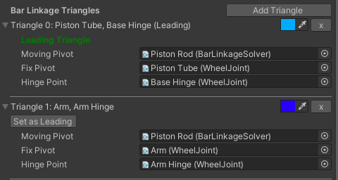
Bar Linkage Triangles | |
Visualize in Scene View | If triangles should be visualized in scene view. |
Create Triangle | Allows the user to add a new triangle with a random color to the Bar Linkage Solver. |
Triangle ## | Shows the ID of the triangle, the names of the two Wheel Joints in the triangle and whether the triangle is the leading triangle. |
Color Picker | Allows the user to change the color of the triangle. |
Delete Button | Allows the user to delete the triangle from the Bar Linkage Solver. |
Leading Triangle / Set as Leading | If the triangle is the leading triangle, that will be displayed. Else a button will appear to set the triangle as the leading triangle. |
Moving Pivot | The Bar Linkage Solver is the Moving Pivot by default. This is a constant field and is shown for clarity. |
Fix Pivot | Allows the user to assign a Wheel Joint as Fix Pivot. |
Hinge Point | Allows the user to assign a Wheel Joint as Hinge Point. |
Bar Linkage Solver Settings | |
Spline Input field | Defines the DSpline to which the Prismatic Joint is bound to. |
Prismatic Joint Settings | |
Spline Constraint | The DSpline used to constrain this joint. |
Spline Constraint Length | The length of the spline. |
Current Spline Position | Normalized position of the Prismatic joint over the spline between 0 and 1. |
Target Control Point | The Spline point to be used for Update Limit ControlPoint. |
Update Limit Control Point | Updates the Target Control Point to the current spline position. |
How to use - Part A
To create a Kinematic Bar Linkage Solver, you first need the right setup. This setup will include several fixed arms, Wheel Joints and a Piston (this requires a DSpline). Part A of the How to use will guide you through the process of creating this system
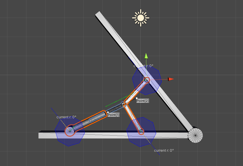
Example of a system suitable for a Bar Linkage Solver.
Add a WIP 2021.1.1208.2 Double Wheel Joint to each of the rotational points

Make sure the Wheel Axis Direction of the Kinematic Wheel Joints are aligned with the desired rotation
After all Kinematic Wheel Joints are added, create a DSpline to control the range and postion of the Piston. Align the Spline Control Points to the Piston Rod. Holding V enables snapping to vertices in Unity
Make sure the DSpline is parented under the Piston. Your system is now set up to add a Kinematic Bar Linkage Solver
...
Add a Body Controller,this can be found under Mechanics > Add Kinematics > Body Controller

Make sure the Kinematic Controller is placed above the system in the Hierarchy
Add a Kinematic Bar Linkage Solver to the prismatic component in the system. This can be found under Mechanics > Add Kinematics > Kinematic Bar Linkage Solver. The prismatic component is the piston part that controls the system
Assign the DSpline as the constraining spline for the Bar Linkage Solver
Create a Triangle
Assign the Fix Pivot and the Hinge Point for the Triangle
Turn on Enforce outside playmode, the first Triangle should work now
Create a second Triangle and follow the same steps
The Kinematic Bar Linkage Solver is now complete
...