...
| Table of Contents |
|---|
...
Overview
The Driven Stepper Motor is a component to simulate an accelerated rotational motion on an axis. It consists of two components; Physical and Logic. Both are needed to control the motor through a logic adapter (connecting the Driven Stepper Motor to an external controller through a Logic Simulator ). Adding a Control Panel gives you the option to control the motor from the Unity scene.
...
A succesfully created Driven Stepper Motor shows up with this gizmo
...
Where to find
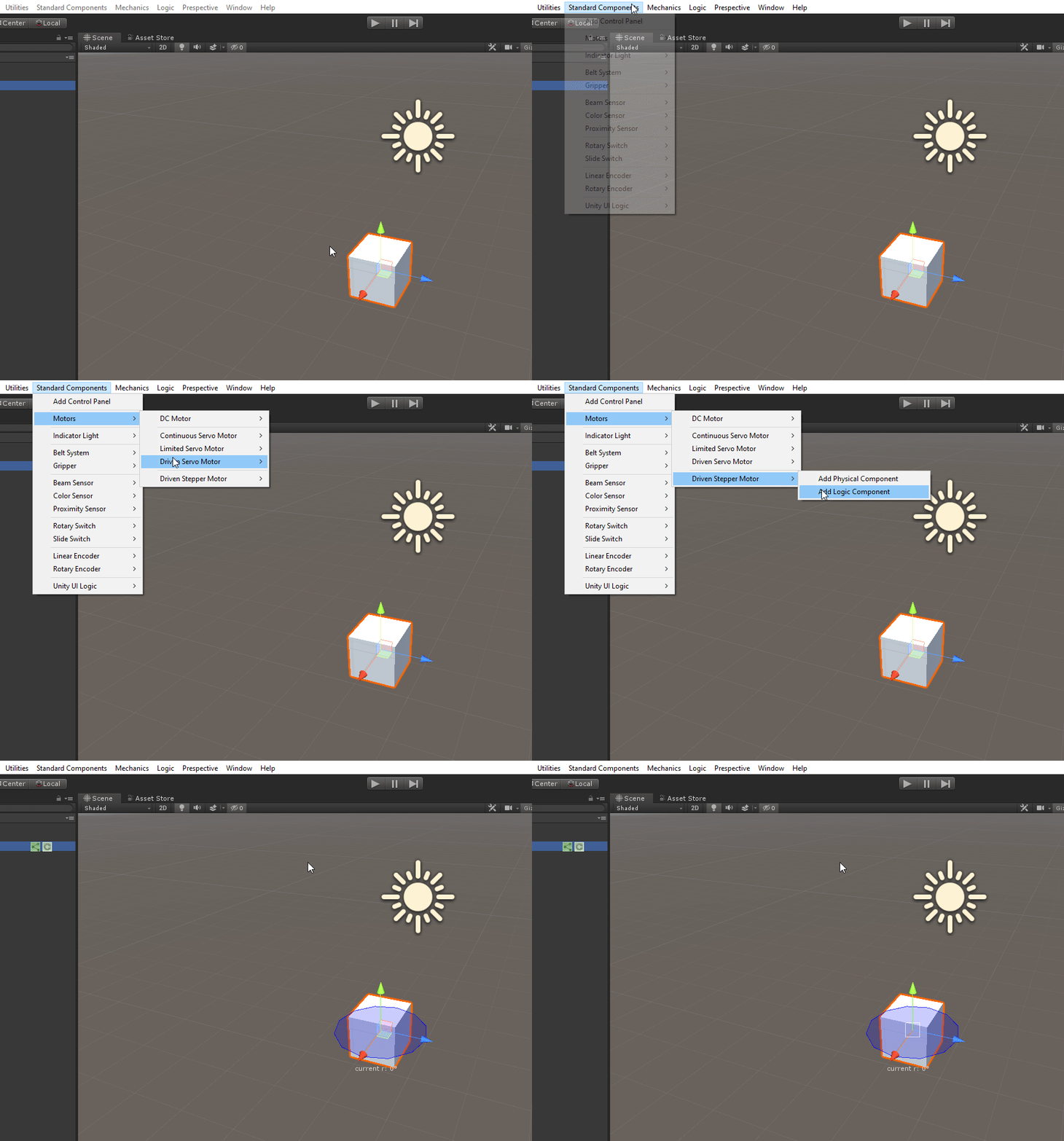
The Driven Stepper Motor can be found under
...
It will automatically be attached to a selected GameObject or otherwise it will create a new GameObject to attach to.
A Wheel Joint will be created automatically as part of the component.
...
Please note: this is an example of a GameObject with the Driven Stepper Motor component
...
Feature Layout - Physical Component
...
Live Data |
|
|---|---|
Preferred Velocity (deg/s) | Displays the current preferred velocity in degrees per second |
Target Step | Displays the step the Driven Stepper Motor will rotate to |
Continuous | Displays whether continuous rotation is enabled (True) or disable (False) |
Continuous Direction | Displays the rotation direction in which the Driven Stepper Motor will rotate when Continuous rotation is enabled. CW = Clockwise, CCW = Counter Clockwise |
Velocity (deg/s) | Displays the current angular velocity in degrees per second |
Position (deg) | Displays the current angle in degrees |
State | Displays whether the Driven Stepper Motor is Active, Inactive or in Error State |
...
Control Panel |
|
|---|---|
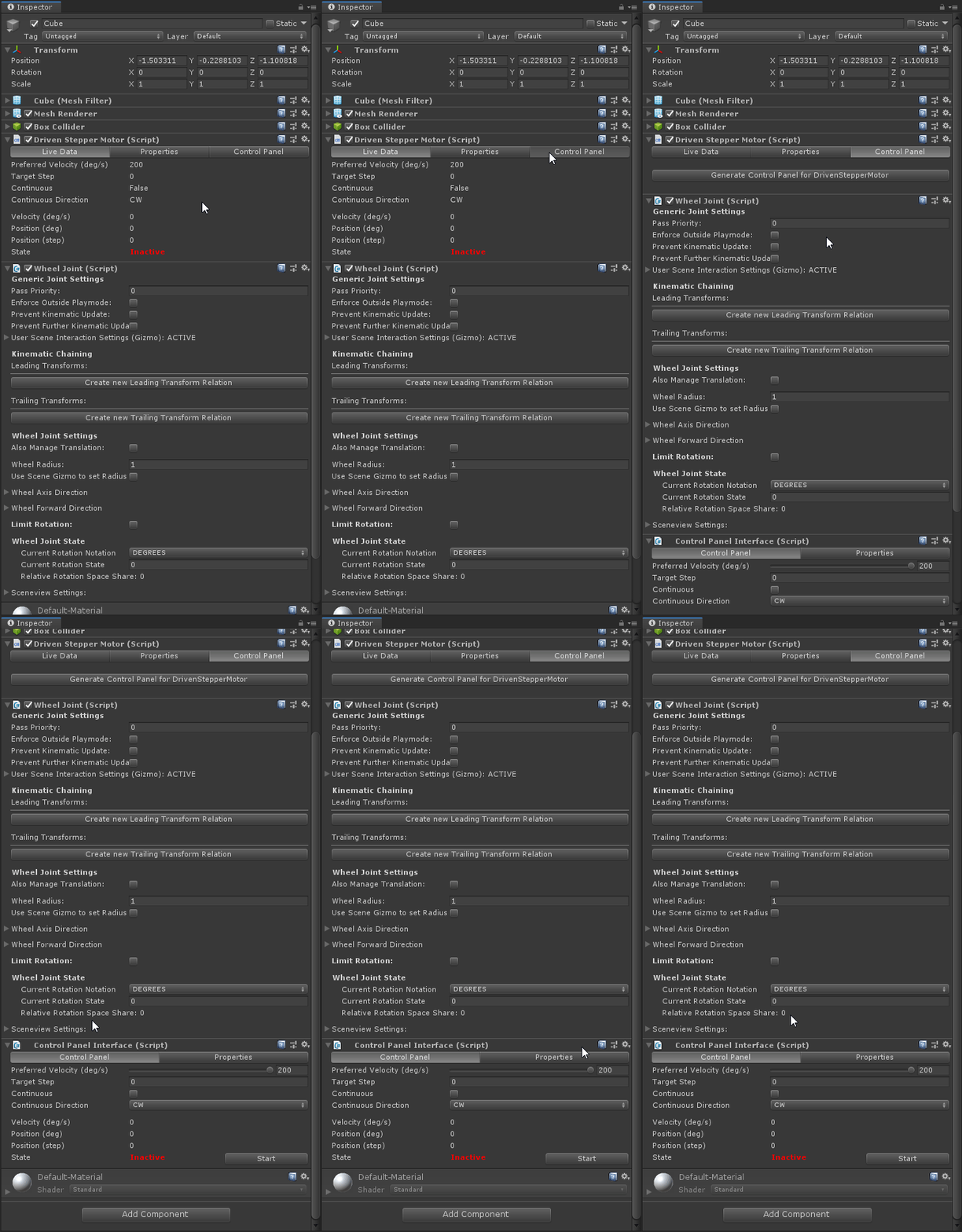
Generate Control Panel for Driven Stepper Motor | Create a Control Panelfor this component |
...
How to use - Physical Component
Add a Driven Stepper Component to a GameObject, in this case a simple cube.
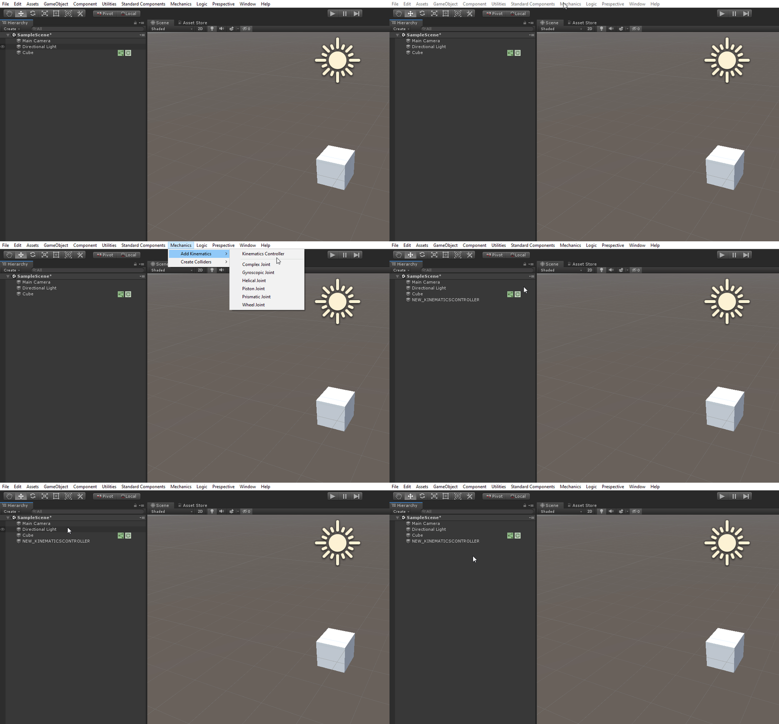
Add a Kinematics Controller,this can be found under Mechanics > Add Kinematics > Kinematics Controller. Make sure the Kinematic Controller is visible in the hierarchy and not connected to the Cube
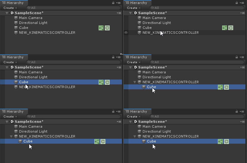
Make sure the Cube is parented under the Kinematic Controller in the Hierarchy
Add a Control Panel
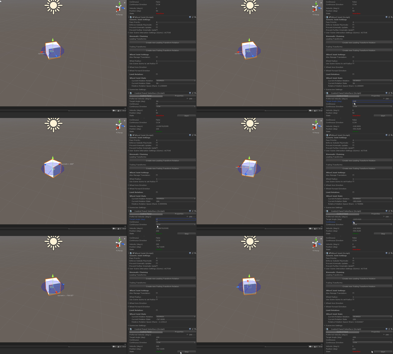
Use the control panel to change settings. Make sure to press Start to start the movement. Note: the component only works in Play Mode
...
Feature Layout - Logic Component
...
Properties |
|
|---|---|
Driven Stepper Motor | Selects a Driven Stepper Motor component you wish to connect to the PLC |
...
PLC Settings and Debugging are general Logic Component settings. Look at the Logic Component Documentation for more details.
...
How to use - Logic Component
Look at the Logic Component Documentation for more details.
...
